|
|||||||||||||||||||||||||||||||||||||||||||||||||||||||||||||||||||||||||||||||||||||||||||||||||||||||||||||||||||||||
|
Antenne verticale Pourquoi une antenne verticale ? Le cahier des charges "antenne" était le suivant : - l'antenne doit être efficace pour le DX, - l'antenne doit être discrète. Si YL a toujours accepté avec beaucoup de compréhension la cohabitation avec la radio, la présence d'un pylone de 40 m n'aurait peut-être pas été accueillie sans réaction... - vu la taille du jardin, la surface au sol doit être inférieure à 1 m², - l'antenne doit offrir peu de prise au vent. Seule une antenne verticale répond parfaitement à tous les critères : faible angle de départ permettant le trafic DX, faible prise au vent, etc. I-Présentation de l'antenne
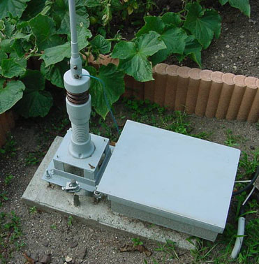
L'antenne verticale utilisée en poste fixe au QTH de F6BLK, est, comme 90 % du matériel de la station, "home made". Cliquer sur la photo pour l'agrandir Cette antenne a été réalisée à partir de matériels des surplus militaires. La base de l'antenne est constituée d'un support MP48 (bien connu des anciens radios de la Gendarmerie) et de huit éléments MS vissés bout à bout qui constituent le brin rayonnant. Ce dernier mesure huit mètres de long. Au delà de six mètres de longueur ce type d'antenne ne peut se maintenir verticalement seul et a la fâcheuse habitude de se courber jusqu'à ce que le sommet de l'antenne touche le sol. Il est donc nécessaire de l'obliger à rester droit par un haubanage léger. Ce dernier a été réalisé avec de la drisse imputrescible de 2 mm utilisée par les marins pêcheurs (produit courant dans les coopératives maritimes ou chez les fournisseurs de matériel de pêche). La prise au vent est minime.
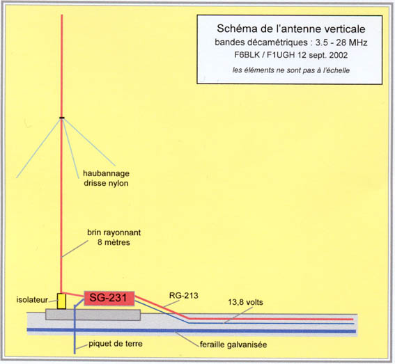
L'embase MP48 est fixée sur un bâti qui a été conçu et réalisé sur mesure par Marcel F1UGH. Le bâti est lui même fixé sur un socle de béton de 80 x40 x 10 centimètres par l'intermédiaire de quatre tiges filetées de 8 mm. L'ensemble est très stable et largement suffisant pour supporter le support, l'antenne et le système d'accord. cliquer sur la photo pour l'agrandir II-Le plan de sol Les antennes verticales sont le plus souvent du type quart d'onde, appelées autrefois type Marconi. Ces antennes doivent impérativement avoir un plan de sol de qualité, ou un système de contrepoids, pour fonctionner correctement. Nous avons choisi la première solution. Sachant que le sol n'est généralement pas de bonne qualité nous avons enfoui dans le sol — à 30 cm de profondeur — des tubes en ferraille galvanisée, reliés entre eux électriquement et à un piquet de terre de deux mètres de long enfoncé dans le sol. Les tubes en ferraille forme dans le sol un "U", l'ensemble des branches du "U" mesure un peu plus de 20 mètres.
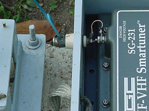
L'alimentation de l'antenne se fait à la base de celle-ci par l'intermédiaire d'une boite d'accord automatique de construction SGC, le "smartuner SG231" SGC. Nous avions utilisé cette boite d'accord de 1998 à 2000 pour alimenter et accorder une antenne Lévy 2 x 20 mètres et feeder twin lead 300 ohms, un balun 1/4 assurant la passage asymétrique (sortie du SG-231) symétrique (twin lead 300 ohms). Nous avons pu apprécier l'extraordinaire souplesse d'utilisation de cette boîte d'accord automatique qui nous permettait d’accorder l'antenne Lévy sur les 9 bandes décamétriques. Sachant que dans ce cas précis la boîte d'accord fait partie intégrante de l'antenne, nous avons essayé d'accorder la verticale en utilisant le SG-231 selon le même principe. Le résultat est excellent et nous pouvons dire aujourd'hui que les résultats ont dépassé toutes nos espérances. IV-Schéma de l'antenne
L'avantage de ce type de montage est d'avoir une antenne qui rayonne sur l'ensemble de sa longueur quelque soit la fréquence d'accord. Elle est donc plus efficace que les antennes verticales à trappes. Nous retrouvons le même souci, faire rayonner l'ensemble de l'antenne, pour les antennes Butternut (HF-6V...) et Cushcraft (R7, R8...). Depuis la mise en place de cette antenne, son utilisation nous a montré qu'elle était particulièrement adaptée au trafic DX (300 pays confirmés au 31/12/2021) et ce avec une puissance output inférieure ou égale à 5 watts HF.
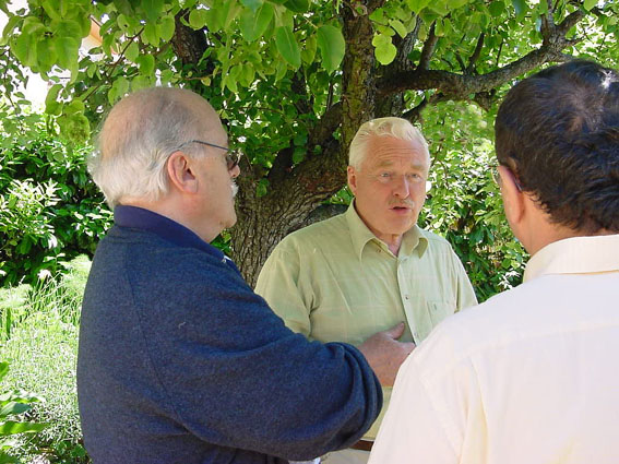
de gauche à droite : F6EBS/Claude, F1UGH/Marcel, F6DUY/Jean-François. Photo F6BLK.
pour revenir à la page d'accueil
|
;)
;)